Thursday, June 21, 2012

How to : DIY Solar Backpack with Solar Mobile phone charger and LED Lighting


Solar Backpack with Solar Mobile phone charger
The Finished Solar Backpack!


Introduction

Last year , i was trekking in the mountains and was surprised by the lack of electricity. Although there was an abundance of sunlight during the day, all lighting there during the evenings/night was with oil lamps which not only smoky but provided very little light. Vowing to return next year better prepared,  i made a solar backpack. It can be also used to power widgets such as the arduino, raspberry pi, etc.  Here are the features:
  • Can charge upto 6 mobile phones at one time!
  • 140 lumen high power led lighting
  • 27wh high capacity battery
  • Modular Design for expansion
DIY solar mobile phone charger
Success!

Materials Required:

Backpack:
  • 5W Solar panel for 6v battery
  • Old Bag / Bagpack
  • General Purpose PCB
  • Schottky Diode (1n5189/ SS14 etc)
  • 6v Sealed Lead Acid battery
  • 2 pin Terminal plug
Solar Mobile Phone Charger Circuit:
  •  5v 3A LDO (I used a ucc383. You can use an LDO with a lower current capacity also)
  • Heatsink for the TO-220 package LDO
  • USB Port
Light engine:
  • High Power led (Can be 1w-3w. I used a CREE XM-L as it is the most efficient led  the world) 
  • Heat Sink for LED
  • Lens/Reflector for the LED
  • LED Driver

Instructions

  • Attach the solar panel to the backpack. You can stitch it, use hot glue, epoxy or any other adhesive as you see fit. I used a synthetic rubber based adhesive called FeviBond.
  • Using a general purpose board, construct the following circuit:
Circuit Diagram for solar mobile phone charger

Circuit Diagram for solar backpack


    • The USB port can be used as a solar mobile phone charger to charge phones, tablets etc.   
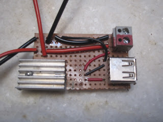
    • My PCB looked like this:
    PCB for solar mobile phone charger

    PCB of Solar Backpack


    • To make the light engine, i soldered some wire to the Cree XML led and mounted it on the heat sink.
    • Although the Cree XML can be driven with 3 Amps or current giving a staggering 1000 lumens, i could not find a suitable driver. Hence, i am using a 350ma driver.
    Power led mounted on heatsink
    Led mounted on heatsink
    • Some LED drivers, for use as halogen replacements have a bridge rectifier.If you wish, you can remove the diodes as they cause a voltage drop of about one volt. I removed them as they reduce efficiency
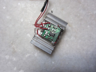
    • Mount the led driver on the other side of the heat sink


    Led driver mounted on a heatsink
    Led Driver mounted on heatsink

    • Attach the reflector or lens to the led. 


    Reflector mounted on a led
    Reflector mounted on the led
    Enjoy your eco-freindly power source! In the picture below, it is a solar mobile phone charger!
    mobile phone being powered by solar panel
    Mobile phone being powered by 100% solar power!

    In the picture below, the Arduino Uno is being powered by the solar backpack, making it a solar powered arduino! You can also use this to power the Raspbery Pi, Teensy etc!

    solar powered arduino
    Solar Powered Arduino


    Tuesday, May 8, 2012

    How to Make an Arduino Solar Tracker : The Light Sensor

    How to Make an Arduino Solar Tracker : The Light Sensor

    One of the most important parts of the solar tracker is the Light Sensor whose job is to accurately detect the position of the sun.

    What is a light dependent resistor or photo-resistor?

    The resistance of a light dependent resistor or photo-resistor changes according to the intensity of the light. In other words, the resistance of the LDR is inversely proportional to the light intensity. We shall use this property to track the sun

    Design of the light sensor

    Circuit diagram

    Circuit Diagram: Light Sensor for an Arduino Solar tracker
    Circuit Diagram: Light Sensor for an Arduino Solar tracker
    The light sensor works by creating a voltage divider by using a fixed resistance, in this case a 15 kilo-ohm resistor and an LDR. The value of the resistor was chosen as the illuminated resistance of my LDR was approximately 12 kilo-ohm. The corresponding voltage created is fed to the ADC of the arduino. Since the one end of the LDR was tied to ground, an increase in illumination would correspond to a higher ADC output

    Physical Design
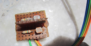
    light sensor arduino
    Mechanical aspect of light sensor design
    The light sensor was constructed on a piece of perfboard with some ribbon cable for easy connectivity to the Arduino.
    The light sensor  is in a T shaped design with a piece of perfboard/veroboard perpendicular between the two LDRs. The reason for the "divider" is that if the position of the son is on either side of the light sensor, a shadow will fall on one sensor and only the LDR facing the sun will be illuminated

    Connecting it to the Arduino and the Software
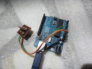
    solar tracker arduino light sensor
    Connection of light sensor to arduino
    The outputs form both the LDR are connected to ADC pins AnalogPin0 and AnalogPin1 of the arduino. 
    Here is a simple arduino sketch that reports the value of both the LDRs and reports it on the serial monitor


    /* 
    LDR Calibration test for solar tracker 
    Sketch by Sarang Gupta
    For more info visit www.mysolaradventures.com
    */


    int ldr1 = 0;            //LDR1 is connected to analog pin0
    int ldr2 = 1;            //LDR2 is connected to analog pin1
    int ldr1_value = 0;        //variable to store LDR1 values
    int ldr2_value = 0;        //variable to store LDR2 values

    void setup()
    {
      Serial.begin(9600);   //start outputting data to serial monitor
    }

    void loop()
    {
      ldr1_value = analogRead(ldr1);          //reads the light hitting LDR1
      ldr2_value = analogRead(ldr2);          //reads the light hitting LDR2
      Serial.print("LDR1 reading= ");
      Serial.println(ldr1_value);                 //prints the LDR values to serial monitor
      Serial.print("LDR2 reading= ");
      Serial.println(ldr2_value);                 //prints the LDR values to serial monitor
      delay(50);                  //wait for 50 ms
    }


    In the next post i will outline the actuator for the solar panel and a video of the final working tracker!

    Friday, April 20, 2012

    How to Make an Arduino Solar Tracker : Part 1

    In the next couple of days i will be making an arduino solar tracker. The is the first post in the series of posts in which i show you how to make an arduino solar tracker

    What Are Solar Trackers?

    It is a well known fact that solar panels give maximum power when the incident ray from the sun hits the solar panel perpendicularly. Hence if a solar panel is kept along the ground, it will give maximum output during the noon when the solar radiation is maximum and the suns rays strike it perpendicularly. 


    solar panel output
    Formula for calculating solar output

    This is where solar trackers come in. Solar trackers follow the sun, just like a mechanical sunflower. I will be building a single axis arduino powered solar tracker which tilts the solar panel in the direction of the sun. Using a solar tracker increases the output of a solar panel by 50 to 60 percent although it may not be practical at all scales and sizes.

    Thursday, April 12, 2012

    How to make a solar cell using diodes

    So the other day while i was studying about solar cells, i realized that a photovoltiac solar cell is very similar to a standard silicon diode, they are both p-n junctions, the only difference  being that a solar cell has a higher surface area. So i decided to use an 1N4148 standard small signal rectifier with an exposed die. I connected it to a Multimeter to check the voltage coming out of the diode. To my surprise, it worked! After concentrating the light to the diode with a magnifying glass, i was a able to get a usable voltage from the diode

    Although i doubt that this would be more efficient than a standard photovoltiac cell, i believe that this might be useful in low cost applications
    Please feel free to give any suggestions and improvements in the comments

    Thank for watching!

    EDIT: I got featured on Hackaday.com!